Regularizing Signals
Plaquette provides expressive, automated, and robust ways to deal with signals for interactive design using regularization filters such as smoothing, min-max scaling, and normalization.
Direct Input-to-Output
Let’s review briefly how to handle raw input and output signals in Plaquette. We will be using an analog sensor such as a photoresistor for this example.
Note
In order to build this circuit, you will need to create a simple voltage divider circuit. Connect the photoresistor between the ground (GND) and the analog input pin (A0`). Then connect a fixed resistor with value matching your photoresistor between analog input pin and +5V (Vcc). For example, for a 1k \(\Omega\) - 10k \(\Omega\) photoresistor you could use a fixed resistor of about 5.5k \(\Omega\)).
Here is a simple Arduino code that allows one to change the value of an output LED using an input photocell:
// The photocell analog pin.
int photoCellPin = A0;

// The output analog LED pin.
int ledPin = 9;

void setup() {
  // Initialize pins.
  pinMode(photoCellPin, INPUT);
  pinMode(ledPin, OUTPUT);
}

void loop() {
  // Read value from photocell (between 0 and 1023).
  int value = analogRead(photoCellPin);

  // Write value to LED (between 0 and 255).
  analogWrite(ledPin, value / 4);
}
As explained in Why Plaquette? section, this simple code is made complicated by the fact that the programmer needs to remember low-level information concerning the ranges of raw number values (1023, 255, …) Furthermore, this code fails to adapt to changing conditions such as the range of the ambient light.
Let’s see how Plaquette can help us to create more expressive code by using inputs and outputs signals rather than meaningless raw numbers.
To begin, we will re-implement the example above using Plaquette units.
First, let’s define our input photocell on pin A0 using an AnalogIn unit:
AnalogIn photoCell(A0);
Then, let’s add an output analog LED on pin 9 using an AnalogOut unit:
AnalogOut led(9);
If we want to directly control the value of the LED from the value of the photocell, all we need to do is to send the photocell’s value to the led. The easiest way to do so is by using the >> operator:
photoCell >> led;
The complete Plaquette code will look like this:
#include <Plaquette.h> // include the Plaquette library

// Create input unit for photocell.
AnalogIn photoCell(A0);

// Create output unit for LED.
AnalogOut led(9);

void begin() {}

// Define frame-by-frame operations.
void step() {
  // Send photocell value directly to the LED.
  photoCell >> led;
}
Getting the Full Range of a Signal
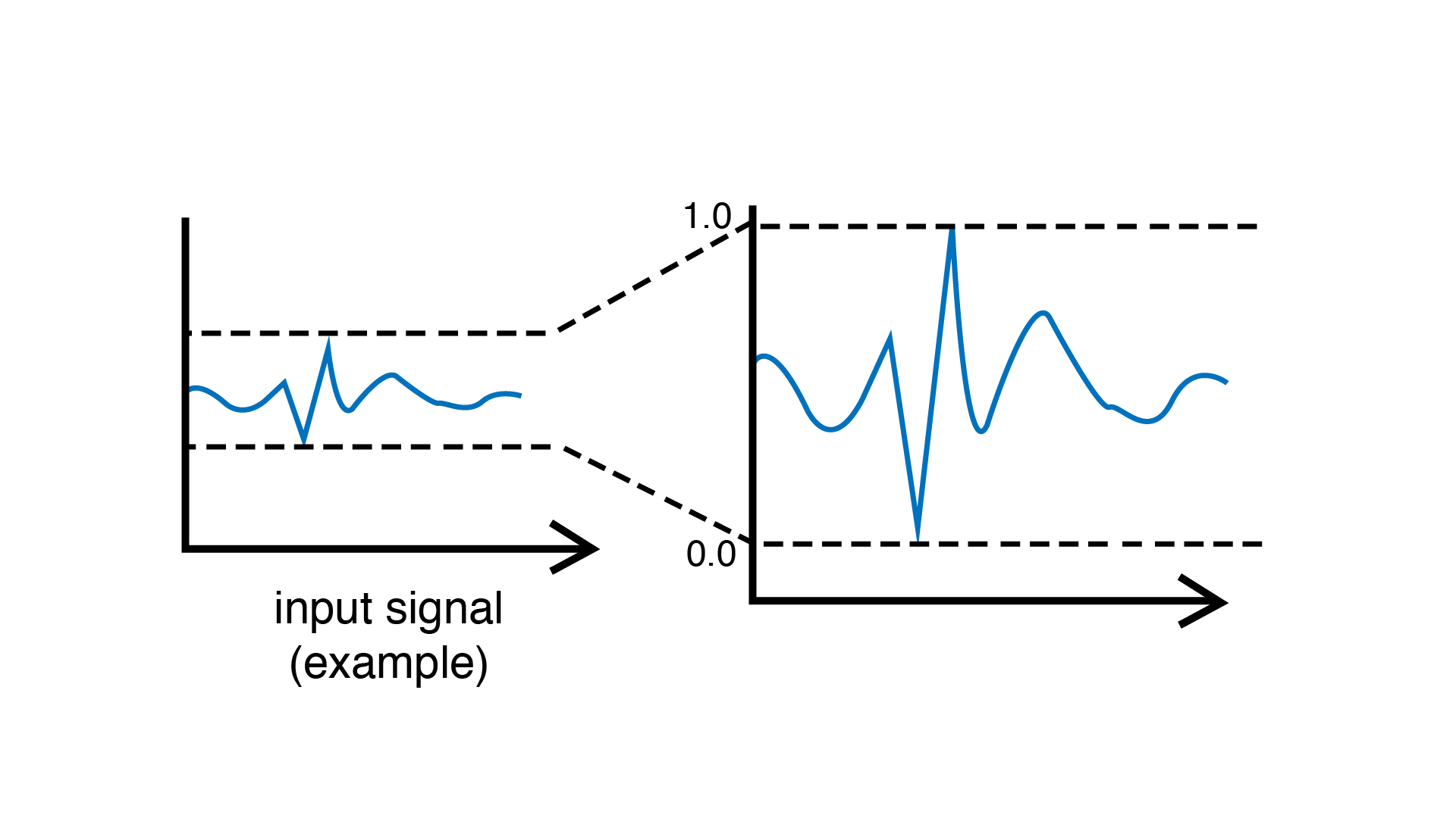
If we run this program, we will likely notice that the LED brightness will not span the full range from 0% to 100%. That’s because depending on ambient lighting conditions, the photocell’s values will not move across the full spectrum of possibility. For instance, in the dark, the photocell might range from 10% to 50%, while in full daylight, it might range between 70% and 95%.
In order to resolve this issue, we need to regularize the photocell’s signal. We can do so using a filtering unit such as a MinMaxScaler. This unit automatically keeps track of the minimum and maximum values of the incoming signal over time (for example, 10% and 50%) and remaps them into a new interval of [0, 1] (ie., 0% to 100%).
To use this approach, create the unit:
MinMaxScaler regularizer;
… and then insert it in the pipeline between the incoming photocell signal and the output LED:
photoCell >> regularizer >> led;
The above expression will do the following, in order:
Read the raw photocell value using the
photoCellunit.Send that raw value from the
photoCellunit to theregularizerunit.The
regularizerunit updates itself if the value is a new extreme value (minimum or maximum).The
regularizerthen remaps the raw photocell value to the full range of [0, 1] and sends it to theledunit.The
ledunit takes the input value in [0, 1] and applies it to the intensity of the LED.
Reacting to Signal Changes
Remember our example from ealier, where we were trying to detect high-valued signals using arbitrary numbers?
if (value > 716)
  // do something
Suppose that instead of directly controlling the LED value based on the photocell’s value, we instead want to use sudden changes in the photocell’s value to trigger the on/off state of the LED? In other words, we would like to work with the peaks in the incoming signal (such as when someone points a light source towards the photocell).
One way to do so would be to pick a threshold in the regularized signal
above which we would react to the light source. Let’s say that we will react
when the signal goes above 70%. The code of the step() function now
becomes:
void step() {
  photoCell >> regularizer;
  if (regularizer > 0.7)
    1 >> led;
  else
    0 >> led;
}
… which can be more compactly rewritten by sending directly the conditional
expression (regularizer > 0.7) to the output LED:
void step() {
  photoCell >> regularizer;
  (regularizer > 0.7) >> led;
}
Adapting to Changing Conditions
So far so good. The number 0.7 is still a bit of an arbitrary, hand-picked number, but it makes more sense than 716 because it refers to a more human-understandable concept (70% instead of 716 / 1023). However, this approach will still be sensitive to changes in the ambient light, and behave differently under different light conditions (for example, it might work as expected in the morning, but work less well in the late afternoon when the sun starts to go down.)
One thing we could do would be to make sure that our regularization unit adapts to changing conditions. In order to do this, rather than having our MinMaxScaler remap values depending on every single incoming value, we can have it adapt over a time window. This will allow our regularizer to slowly forget what it has learned, and reprogram itself after a certain amount of time has passed.
This can be accomplished by calling the timeWindow(seconds) function inside
the begin() function:
void begin() {
  // Allow regularizer to adapt over an approximate period of 1 hour (3600 s).
  regularizer.timeWindow(3600.0f);
}
Normalizing Signals to Spot Extreme Values
The MinMaxScaler is a very useful unit for making sure signals stay within a [0, 1] range. However, it is not always the best for signal detection since it only accounts for extreme values (minimum and maximum), which makes it sensitive to rare events. Someone switching the lights on and off again rapidly might completely ruin the show.
A better alternative is the Normalizer unit, which regularizes incoming signals by normalizing them around a target mean by taking into account standard deviation. Once the data is normalized, extreme outlier values can be more easily and robustly detected based on how much they diverge from the mean.
Let’s replace our MinMaxScaler by a Normalizer unit:
Normalizer regularizer;
… and use the isHighOutlier() function to find values that are higher
than usual:
void step() {
  photoCell >> regularizer;
  regularizer.isHighOutlier(photoCell) >> led;
}
Tip
By default, the isHighOutlier() function detects values that are more than
1.5 deviations from the mean. The function can be made more or less sensitive by
adjusting the number of deviations (typically between 1.0 and 3.0). For example,
isHighOutlier(value, 1.2) will be more sensitive,
isHighOutlier(value, 2.5) will be less sensitive, and isHighOutlier(value, 3.0)
will only respond to rarely-occuring extremes. While these numbers (1.2, 1.5, 2.5, etc.)
still need to be hand-picked, they are much more robust than our 716 and even to
our 0.7 number from earlier.
Here is a complete version of the code:
#include <Plaquette.h> // include the Plaquette library

// Create input unit for photocell.
AnalogIn photoCell(A0);

// Create output unit for LED.
AnalogOut led(9);

// Create regularization object.
Normalizer regularizer;

// Initialize everything.
void begin() {
  // Allow regularizer to adapt over an approximate period of 1 hour (3600 s).
  regularizer.timeWindow(3600.0f);
}

// Define frame-by-frame operations.
void step() {
  // Update regularizer with raw signal value.
  photoCell >> regularizer;

  // Detect outliers and send the value (1=true=outlier, 0=false=no outlier)
  // directly to the LED.
  regularizer.isHighOutlier(photoCell) >> led;
}
Detecting Peaks
The outlier detection method is useful to find extreme values. However, it also
comes with an important limitation. The isHighOutlier() and isOutlierLow()
methods return true as long as the received value is considered to be an
outlier, making these methods unsuitable for triggering instantanous events, such as
toggling the status of an LED, starting a sound event, activating a motor, etc.
The PeakDetector unit addresses this limitation. It is best used in combination
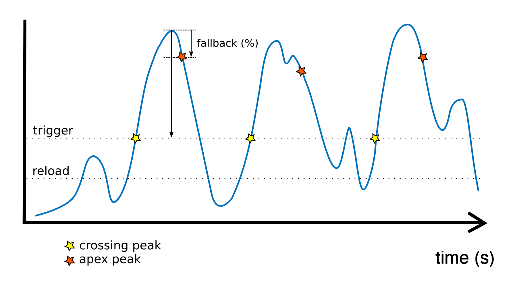
with a Normalizer unit. We will use the default mode of the PeakDetector (PEAK_MAX):
for a peak to be detected. In this mode, the signal will need to (1) cross a trigger threshold value
(triggerThreshold); (2) reach its apex (max); and (3) fall back by a certain
proportion (%) between the threshold and the apex (controlled by the fallbackTolerance
parameter).
Building on the previous section for outlier detection, we will assign the PeakDetector’s
triggerThreshold to the value above which a value is considered to be a high outlier,
which can be obtained by calling the Normalizer’s function highOutlierThreshold():
PeakDetector detector(normalizer.highOutlierThreshold());
Tip
As for the isHighOutlier() function, the highOutlierThreshold() function
is set to return, by default, a threshold that is 1.5 standard deviations from the mean. The
function can be made more or less sensitive by adjusting the number of deviations.
For example, highOutlierThreshold(1.2) will be more sensitive, while
highOutlierThreshold(2.5) will be less sensitive.
Finally, let’s rewrite the step() function with our new peak detector, so
that only when a peak is detected will the LED change state:
void step() {
  // Signal is normalized and sent to peak detector.
  sensor >> normalizer >> detector;

  // Toggle LED when peak detector triggers.
  if (detector)
    led.toggle();
}
The PeakDetector unit offers many options to fine-tune the peak detection process. Please read the full documentation of the unit for details.
Conclusion
The Plaquette library simplifies signal processing for interactive design by abstracting low-level details and offering intuitive regularization tools like MinMaxScaler and Normalizer. Combined with PeakDetector opens the way to deploy precise event-driven behaviors.
Plaquette’s ability to adapt to changing conditions ensures dynamic, robust systems while keeping code concise and expressive. By leveraging its modular architecture, users can streamline signal handling, improve scalability, and focus on innovation in signal-driven creative applications.